297 Results
View results:
Sort by:

For structural components consisting of slabs, it is necessary to perform shear design on the locations with concentrated load introduction, applying the punching shear design rules according to Sect. 6.4 of EN 1992‑1‑1 [1]. The concentrated load introduction is present on the individual locations, for example by columns, concentrated load, or nodal supports. In addition, the end of linear load introduction on slabs is also regarded as concentrated load introduction. For example, this includes wall ends, wall corners, and ends or corners of line loads and line supports. You can perform the punching shear design for floor slabs or foundations, considering the existing available plate topology about the designed node of punching shear. The punching shear design according to EN 1992‑1‑1 checks that the acting shear force vEd does not exceed the resistance vRd.
![Time-Dependent Settlement Components [2]](/en/webimage/009673/2419908/01-en-png-png.png?mw=640&hash=5e657e3feb5c1bb6d21727468dd85d91e1c9f29f)
For the serviceability limit state design according to Section 6.6 of Eurocode EN 1997‑1, settlement has to be calculated for spread foundations. RF-/FOUNDATION Pro allows you to perform the settlement calculation for a single foundation. For this, you can chose between an elastic and a solid foundation. By defining a soil profile, it is possible to consider several soil layers under the foundation base. The results of the settlement, foundation tilting, and vertical soil contact stress distribution are displayed graphically and in tables to provide a quick and clear overview of the calculation performed. In addition to the design of the foundation settlement in RF-/FOUNDATION Pro, the structural analysis determines the representative spring constants for the support and can be exported to the structural model of RFEM or RSTAB.
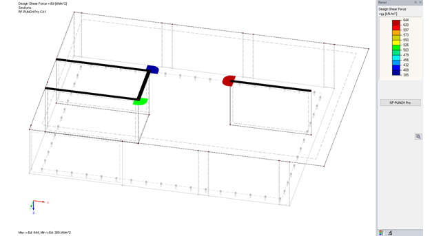
The RF-PUNCH Pro add-on module allows you to perform punching shear design of slabs and foundation plates (floor slabs) on wall ends and wall corners.

In this example, the design resistance of an end plate according to EN 1993-1-8 [1] is to be determined; the other components are not described here. To check the results, the dimensions of the connection IH 3.1 B 30 24 of Typified Connections [2] were used. S 235 material and bolts with strength 10.9 are used.
The efficient design of prestressed structural components requires a few additional steps that go beyond the standard reinforced concrete design, from modeling tendons to the calculation of equivalent loads to the cross-section resistance design. Therefore, it is important that the software for prestressed concrete design is structured and the navigation is possible in the program. RFEM with two add-on modules RF-TENDON and RF-TENDON Design fulfills these requirements and allows engineers to carry out the complete design of prestressed beams, frames, plates, buildings and bridges according to EN 1992-1-1 with National Annexes and SIA 262.
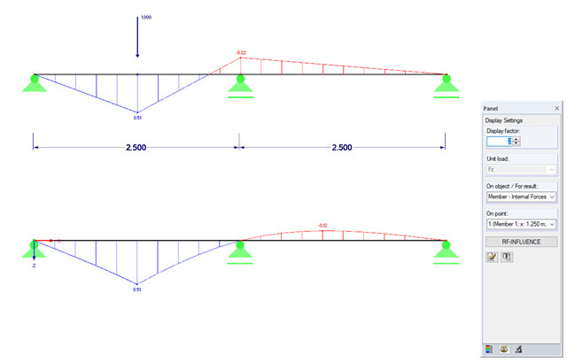
Influence lines are less important nowadays due to fast computer systems. However, it might be an advantage to use influence lines in the phase of preliminary design, as well as in the actual creation of the structural designs. With the RF-INFLUENCE add-on module, influence lines and influence surfaces can be generated and evaluated easily due to a fixed internal force. This technical article describes, with a simple example, the basics of determining and evaluating influence lines.
![Parameters of Effective Slab Width (Figure 5.3 [1])](/en/webimage/009561/2419376/01-en-png.png?mw=640&hash=c76563b459152b19c98197ea6ba342be89d9a5bc)
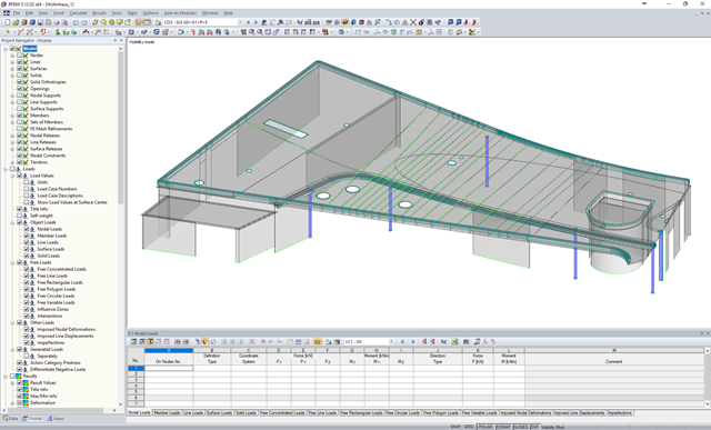
In the case of combined FEM structures (surface and member elements) as well as folded plate structures, it is possible to attribute a beam structure for the design on a member to a fictitious T-beam cross-section, whose geometry depends on the effective width. When using the "Rib" member type in RFEM, the stiffness is represented by a slab component (surface element) and a web component (member element). This approach has some design specifics that are explained in this article.

The RF-/STEEL EC3 add‑on module performs a detailed cross‑section classification on each design before the design is carried out. Thus, the susceptibility to local buckling of all cross-section parts is evaluated. The defined cross-section class has an effect on the resistance and rotational capacity determination.

The following article describes the design of a single-span beam subjected to bending and compression, which is performed according to EN 1993‑1‑1 in the RF-/STEEL EC3 add-on module. Since the beam is modeled with a tapered cross-section and thus it is not a uniform structural component, the design must be performed either according to General Method in compliance with Sect. 6.3.4 of EN 1993‑1‑1, or according to the second-order analysis. Both options will be explained and compared, and for the calculation according to the second-order analysis, there is an additional design format using Partial Internal Forces Method (PIFM) available. Therefore, the design is divided into three steps: design according to Sect. 6.3.4 of EN 1993‑1‑1 (General Method), design according to the second‑order analysis, elastic (warping torsion analysis), design according to the second‑order analysis, plastic (warping torsion analysis and Partial Internal Forces Method).

Utilize the RF-/STEEL Cold-Formed Sections module extension to perform ultimate limit state designs of cold-formed sections according to EN 1993-1-3 and EN 1993-1-5. In addition to the cold-formed cross-sections from the cross-section database, you can design general cross-sections from SHAPE-THIN.